Build it yourself
In order to build and test the sample, a running instance of WebSphere Integration Developer v7.0 including an appropriate WebSphere Process Server unit test environment (UTE) installation is required.
To build the first part of the sample, the following steps need to be taken:
- Create a new module.
- Create two product specific business objects and one generic business object.
- Create business graphs for the objects.
- Create and define a relationship.
- Map the business objects.
- Map the business graphs.
- Create interfaces.
- Map the interfaces to each other.
- Assemble the application.
To build the second part, the following needs to be done:
Part One
Create a new module
In WebSphere Integration Developer (WID), open the File menu, select New and then Module. The Create Module dialog will appear as shown below.

Enter RelationshipSample as the module name, leave the defaults for the other offered choices and press the Finish button. A new module will be generated and opened for editing in the Projects panel on the left side. This module will serve as a container for all subsequently created SCA components.
Create two product specific business objects and one generic business object
Expand the RelationshipSample module in the Projects panel, right-click on Data Types and select New and then Business Object from the context menu that appears.
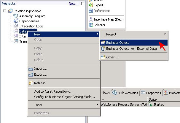
The New Business Object dialog will show up. Enter businessObjects for the folder and DerbyProduct for the name and press the Finish button.

A new business object will be generated using the specified settings and it will be opened for editing.
Press the blue icon button showing the letter F to add a field to the business object.

Enter productKey for the field name and keep string as the corresponding data type. Add two more string fields named productName and productPrice in the same manner.

When done, create two more business objects by following the given procedure. Name the business objects DB2Product and GBOProduct. Please note that GBOProduct will serve
as the generic business object in this sample scenario.
Add three string fields to each of the new business objects to store product information.
As it is recommendable not to use exactly the same field names as for DerbyProduct, assign the following slightly deviating field names for better differentiation:
- identifier, title and price for DB2Product
- productID, productTitle and productPrice for GBOProduct
Save the newly created business objects to preserve all changes.
Create business graphs for the objects
The next step is to create business graphs that enclose the newly defined business objects. Select DB2Product from the list of business objects in the Data Types section in the Projects panel, right-click on it and select Create a Business Graph from the appearing context menu.

An artifact named DB2ProductBG is automatically generated and opened for display. Please note that DB2ProductBG contains a string field named verb in addition to the DB2Product business object. The verb is required to enable operations on the contained object data later on.

Proceed by generating business graphs for DerbyProduct and GBOProduct as well.
Create and define a relationship
Right-click on the module section Transformations in the Projects panel and select New > Relationship.

In the appearing New Relationship dialog, enter relationships for the folder and ProductRelationship for the name. Leave the remaining values unchanged and click the Finish button.

A new relationship is generated and opened for editing. Ignore any shown problem indicators at this point.
Click the Add Role icon button to add a role to the relationship.

A pop-up window will ask for the selection of a data type. Highlight DB2Product and press OK.

Repeat the role creation for DerbyProduct and GBOProduct so that ProductRelationship contains three roles in the end. Any displayed problem indicators can still be ignored.
Select role ProductRelationship_GBOProduct in the Relationship Editor and then open the Details section in the Properties tab. Check the checkbox Managed to mark
the role as being managed.

With role ProductRelationship_GBOProduct still being selected, press the Add key attribute icon button in the Relationship Editor to select a key attribute among the fields of GBOProduct.

Highlight productID in the appearing dialog and confirm the selection by pressing OK. Afterwards, select key attributes for the other roles in the same manner. The key attribute for DerbyProduct should be productKey and for DB2Product, it should be identifier.
Save the relationship to preserve all changes. The previously visible problem indicators should be gone.
Map the business objects
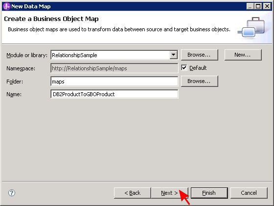
Right-click on the module section Transformations in the Projects panel and select New > Data Map.
The next step is to map the business graphs and objects to each other to define how data should be transformed from one format to another.
In the New Data Map dialog, enter maps for the folder and DB2ProductToGBOProduct for the name and click Next.
Specify DB2Product as input business object in the upper selection panel and GBOProduct as output business object in the lower panel by pressing the corresponding Add buttons. When done, press Finish to close the dialog.

A new business object map will be generated and opened for editing. Draw some transformation wires from left to right just as shown in the following picture.
Select the Relationship transformation to link DB2Product with GBOProduct. In the Details section of the Properties tab, choose ProductRelationship
as the relationship definition and ProductRelationship_DB2Product as the role name.
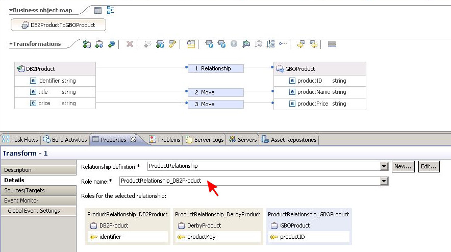
Select Move transformations to map the data stored in the DB2Product fields title and price to the equivalent attributes productName and productPrice
of GBOProduct.
Finally, save the business object map.
Repeat the business object map creation procedure to define the return mapping from GBOProduct to DB2Product as GBOProductToDB2Product and also create maps from DerbyProduct to GBOProduct (DerbyProductToGBOProduct) and the other way around (GBOProductToDerbyProduct).
Map the business graphs
Create another data map but this time for business graphs. In the New Data Map dialog, enter maps for the folder and DB2ProductBGToGBOProductBG for the name and
click Next.
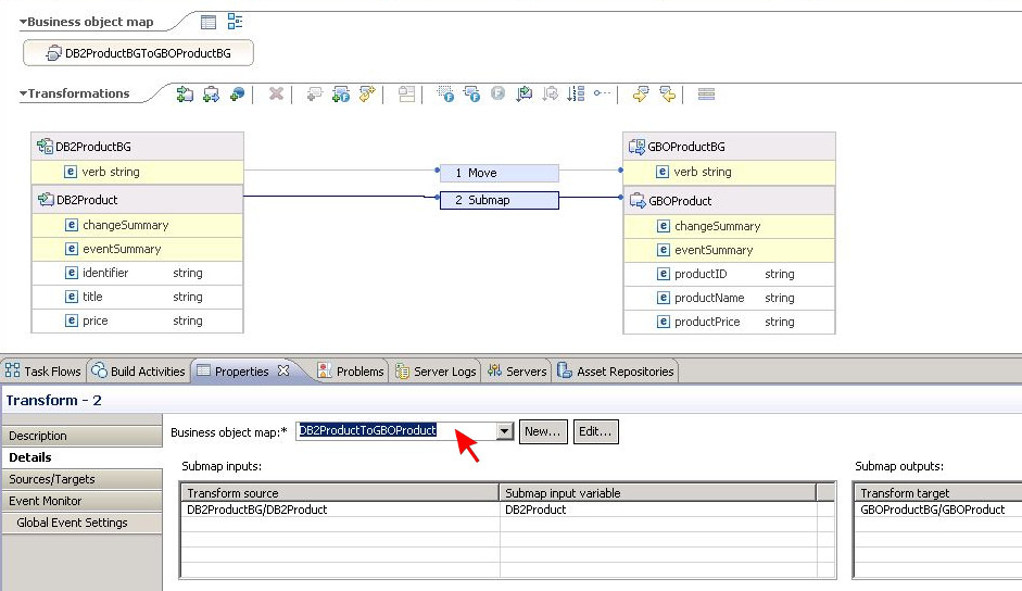
As implied by the map name, specify DB2ProductBG as input business object and GBOProductBG as output business object. Then press Finish.
When the Data Map Editor opens up, wire the verb of DB2ProductBG to the verb of GBOProductBG. Select Move for the transformation in between. Afterwards, draw another wire from DB2Product to GBOProduct with Submap as the corresponding transformation type. In the Details section of the Properties tab, select DB2ProductToGBOProduct from the drop-down list as the business object map to be used. Save the new business graph map.
Create business graph maps named GBOProductBGToDB2ProductBG, DerbyProductBGToGBOProductBG and GBOProductBGToDerbyProductBG in the same manner by using the denoted graphs for input and output and the corresponding business object maps for the submap respectively.
Create interfaces
Right-click on the module section Interfaces in the Projects panel and select New > Interface.
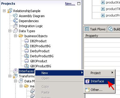
Enter interfaces as the folder and DB2Interface as the name in the resulting pop-up dialog. Keep the default values for all other fields and press Finish.

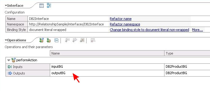
In the Interface Editor, press the icon button Add Request Response Operation to supplement the new interface with a two-way operation. Name the operation performAction. Define a business graph instance named inputBG of type DB2ProductBG as the operation input parameter and another instance named outputBG of the same type as output parameter. Save all changes to the interface when done.
Create further interfaces named DerbyInterface and GenericInterface with equally named operations. Use DerbyProductBG and GBOProductBG as the parameter types respectively.
Map the interfaces to each other
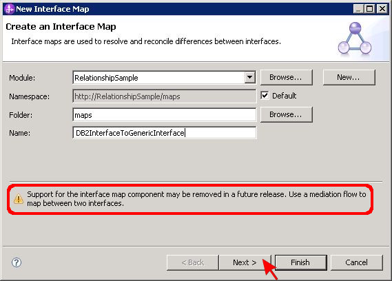
Right-click on the module section Transformations in the Projects panel and select New > Interface Map.
A pop-up dialog will appear. Enter maps as the folder and DB2InterfaceToGenericInterface as the name. Don't change any of the other values.
In WebSphere Integration Developer release 7.0, the dialog also contains a notice informing about the deprecation of interface maps. That is a warning message with no immediate
impact and will be ignored in this first part of the sample. Refer to the second part for details on how to replace interface maps with mediation flows
in order to get rid of that warning.
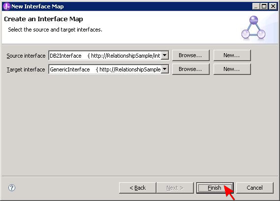
Click Next to proceed. Choose DB2Interface as source interface and GenericInterface as target interface and then press Finish to close the dialog.
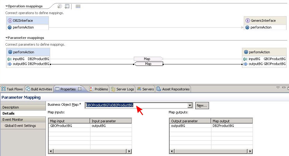
In the Interface Map Editor, draw an arrow from the performAction operation in DB2Interface to its equivalent in GenericInterface. This needs to be done to
further detail the operation mapping.
Click on the arrow to display the corresponding parameter mappings. Draw another arrow from left to right to link the parameter inputBG of type DB2ProductBG with the parameter
inputBG of type GBOProductBG. Draw one more in the opposite direction to connect the parameter outputBG of type GBOProductBG to its equivalent of type DB2ProductBG.
Make sure that for both parameter mapping arrows, the parameter mapping type is set to Map. This can be done in the Description section of the Properties tab when the arrow
is selected. In the Details section of the same tab, use the given drop-down list to pick an appropriate business object map for the mapping. This action must be performed for both parameter
mapping arrows, too.
Finally, save the newly created interface map.
Create one more interface map named DerbyInterfaceToGenericInterface in the same manner to define a mapping between DerbyInterface as input and GenericInterface as output.
Assemble the application
Save all open files and take a look into the Problems tab. There must not be any more errors. If you still see any, please double-check whether you have correctly followed the instructions above.
Open the assembly diagram for module RelationshipSample and drag the interface maps DB2InterfaceToGenericInterface and DerbyInterfaceToGenericInterface from the
Projects panel on the left side onto the blank diagram canvas.
The relationship can be tested using only the interface maps but in order to yield telling test results, each map must be linked to an implementation. Open the Components section in the
palette to the left of the diagram and drag two Java components onto the canvas. The components will automatically be named Component1 and Component2. Wire the reference part of
DerbyInterfaceToGenericInterface to Component1 as shown in the following picture.

This wiring will result in a confirmation dialog popping up. Press OK to accept that a matching interface is created on the target component.
Afterwards, connect DB2InterfaceToGenericInterface to Component2 in the same manner.

Finally, save the assembly diagram. You may test the sample at this point or proceed with part two.
Part Two
Migrate the interface maps to mediation flows
Open the assembly diagram for module RelationshipSample. There are two interface maps named DB2InterfaceToGenericInterface and DerbyInterfaceToGenericInterface, each wired to a Java component. The next step is to transform these interface maps into equivalent mediation flows. This can be achieved using two different approaches.
Option 1: The automated approach
Right-click on interface map DB2InterfaceToGenericInterface in the assembly diagram. From the appearing context menu, select the option Migrate to Mediation Flow.

A confirmation dialog will show up. Click Yes to continue. Immediately, a new mediation flow also named DB2InterfaceToGenericInterface is automatically generated and the interface map is replaced with that new flow in the assembly diagram. Repeat the automatic migration for DerbyInterfaceToGenericInterface. The assembly diagram should contain no more interface maps afterwards. Save your changes.
Please note that while the automatic migration works fine in this sample case, it may result in runtime problems for more complex scenarios. If module tests fail after an automatic migration,
please read the following technote for troubleshooting advice:
Relationship workflows fail when used interface maps are converted to mediation flows in WebSphere Process Server (WPS) Version 7
Option 2: The manual approach
Before starting with the manual procedure, remove all elements from the assembly diagram. In order to do this, select each element and then press the Delete (DEL) button on your keyboard.
Press Yes in the appearing confirmation dialogs to confirm your decision.
Begin the mediation flow creation by expanding the RelationshipSample module in the Projects panel, right-click on Integration Logic and select New and then Mediation Flow from the context menu that pops up.

In the New Mediation Flow dialog, enter maps for the folder and DB2InterfaceToGenericInterface as the name. Remember that this mediation flow is supposed to replace the interface map DB2InterfaceToGenericInterface. The interface map can be removed once the mediation flow is fully defined, so it is acceptable to use the same name for both components here.

Click Next and select DB2Interface as the source interface and GenericInterface as the target reference using the given Add buttons. When done, click Finish to close the dialog.

The Mediation Flow Editor will open to show the newly generated flow. Click on the operation performAction below DB2Interface. A yellow window will appear, offering several mediation flow templates to be used. Choose Operation Map by clicking the corresponding text link.

Select performAction as the reference operation in the next dialog and press OK. The Mediation Flow Editor will switch to a view of the flow's request branch, showing an input primitive wired to a callout primitive with a map component named input_map in between.

To the left of the flow diagram, the Palette can be found. Open its Transformation section and drag a Business Object Map component into the diagram. The component will be displayed as BOMapper1.

Delete component input_map and wire BOMapper1 to the input and callout primitives instead. The diagram should now look as in the following picture.

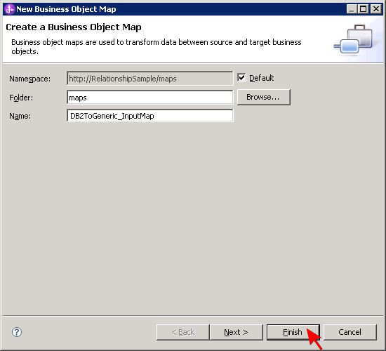
Double-click on BOMapper1 to supplement the component with an implementation. In the New Business Object Map dialog, enter maps for the folder and DB2ToGeneric_InputMap as the name and click Finish.
Another editor will open to show a diagram containing the newly generated business object map skeleton. There are two objects named performActionRequestMsg, both containing an element
named performAction. Click on the node icons in front of both element names to expand the corresponding sections and to discover the included elements named inputBG.
Wire the inputBG element of type DB2ProductBG to its equivalent of type GBOProductBG.

The editor will automatically add a Submap transformation. Click on that transformation in the diagram and then go to the Details section in the Properties tab. From the drop-down menu, pick DB2ProductBGToGBOProductBG as the business object map to be used. Finally save your changes to the business object map.

Now switch back to the Mediation Flow Editor to continue the definition of DB2InterfaceToGenericInterface. Click on the Response tab in the editor window to open the response branch of the mediation flow. Repeat the steps previously taken for the request branch in order to replace the predefined component output_map with a new business object map named DB2ToGeneric_OutputMap. Please note that the objects to be mapped will have slightly deviating names. However, the procedure to implement the output mapping is exactly the same as for the input mapping.

When done with the output mapping implementation, save mediation flow DB2InterfaceToGenericInterface.
Repeat the entire manual procedure to create another mediation flow named DerbyInterfaceToGenericInterface in the same manner.
Finally, open the empty assembly diagram of the module and drag the two mediation flow components from the Projects panel onto the diagram canvas. Then open the Component section of the diagram's Palette and add two Java components to the assembly diagram. Wire each of the mediation flows to one Java component. During that operation, a dialog box will pop up stating that a matching interface would be created on the target. Press OK to take this last step in the manual approach.
Save all open files and take a look into the Problems tab. There must not be any more errors. If you still see any, please double-check that you have correctly followed the instructions above.
Run the sample to verify that it works as expected.