2.5-inch model
There are the right EIA assembly and the left EIA assembly on the server, use the following steps to remove them.
For the right EIA assembly
- Read the safety information that begins on Safety and Installation guidelines.
- Turn off the server and peripheral devices, and disconnect the power cord and all external cables.
- Remove the cover (see Removing the top cover).
- Remove the fan cage assembly (see Removing the fan cage assembly).
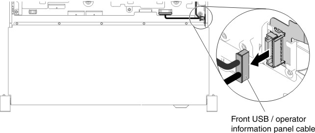
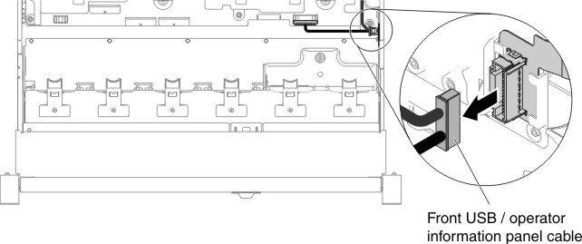
- Disconnect the front USB/operator information panel cables form
the connector mounted on the chassis side.Note: Disengage all latches, release tabs or locks on cable connectors when you disconnect all cables from the system board. Failing to release them before removing the cables will damage the cable sockets on the system board. The cable sockets on the system board are fragile. Any damage to the cable sockets may require replacing the system board.Figure 1. Front USB/operator information panel cable removal
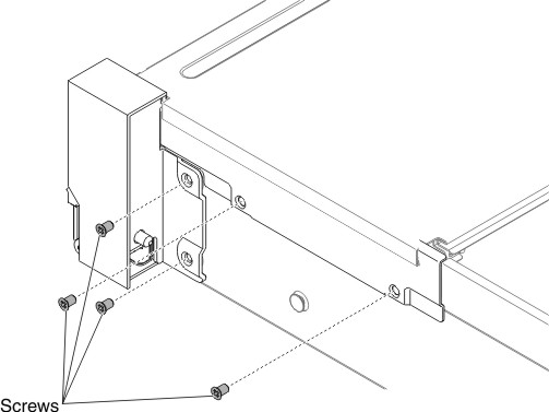
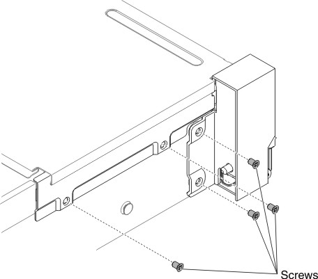
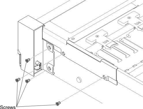
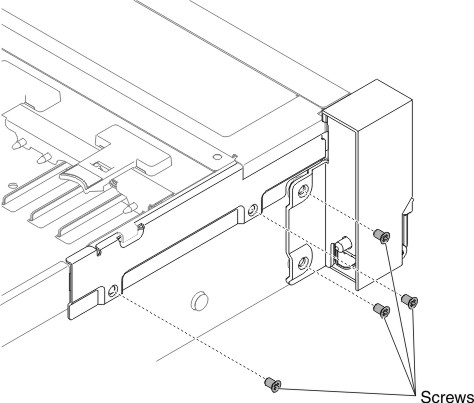
- Loosen screws and remove them.Figure 2. Screw removal
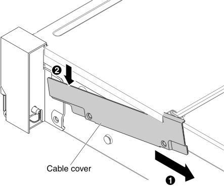
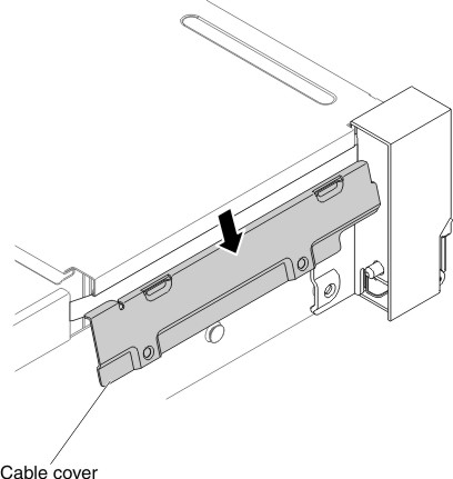
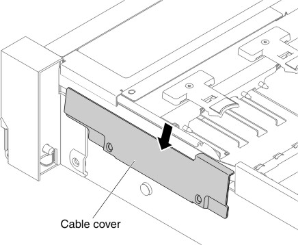
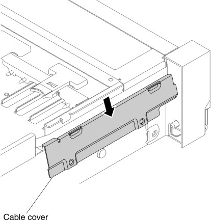
- Tilt the cable cover and remove it from the server.Figure 3. Cable cover removal
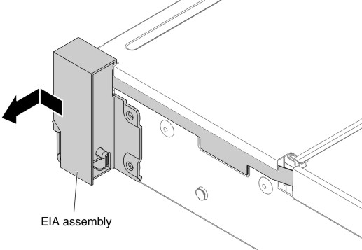
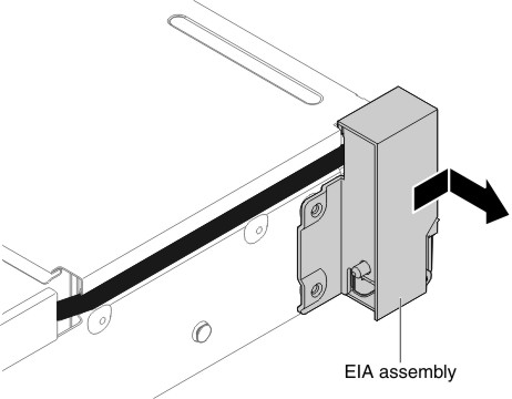
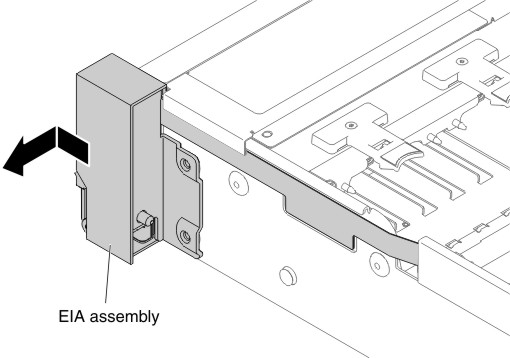
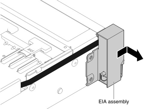
- Grasp the EIA assembly and pull it slightly forward to remove
it from the server.Figure 4. EIA assembly removal
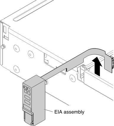
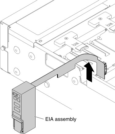
- Position the EIA assembly as shown in the following illustration;
then, remove the assembly out of the server.Figure 5. EIA assembly removal
- If you are instructed to return the EIA assembly, follow all packaging instructions, and use any packaging materials for shipping that are supplied to you.
For the left EIA assembly
- Read the safety information that begins on Safety and Installation guidelines.
- Turn off the server and peripheral devices, and disconnect the power cord and all external cables.
- Remove the cover (see Removing the top cover).
- Remove the fan cage assembly (see Removing the fan cage assembly).
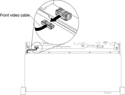
- Disconnect the front video cable from the system board.Note: Disengage all latches, release tabs or locks on cable connectors when you disconnect all cables from the system board. Failing to release them before removing the cables will damage the cable sockets on the system board. The cable sockets on the system board are fragile. Any damage to the cable sockets may require replacing the system board.Figure 6. Front video cable removal

- Loosen screws and remove them.Figure 7. Screw removal
- Tilt the cable cover and remove it from the server.Figure 8. Cable cover removal
- Grasp the EIA assembly and pull it slightly forward to remove
it from the server.Figure 9. EIA assembly removal
- If you are instructed to return the EIA assembly, follow all packaging instructions, and use any packaging materials for shipping that are supplied to you.