To connect the tasks means to wire the tasks.
To wire the tasks, click in the center of the input and output elements you are wiring; otherwise a second input or output port may be created.
- Click the Connections icon
 in the palette, and then click the Input Criterion item
which is a rectangle on the outer left boundary of the canvas. Click the input
of the Check Order Handling for Automatic Approval task. A wire connection is created.
in the palette, and then click the Input Criterion item
which is a rectangle on the outer left boundary of the canvas. Click the input
of the Check Order Handling for Automatic Approval task. A wire connection is created.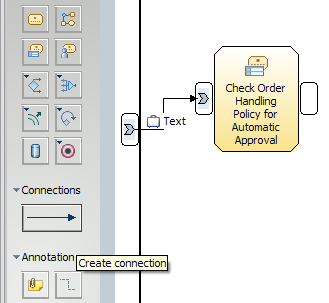
- Click on the arrow icon
 to move out of the connection mode. Right-click the newly
created connection and select Associate Data. Navigate
to the ClipsAndTacksF1 project, select Order, and then
click OK.
to move out of the connection mode. Right-click the newly
created connection and select Associate Data. Navigate
to the ClipsAndTacksF1 project, select Order, and then
click OK. 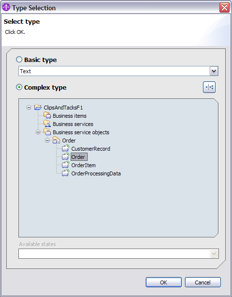
- Wire the remainder of the process diagram by repeating steps 1
and 2 for all of the elements. Review the Tips below before proceeding with
wiring. All of the links must have the Order business item, with the exception
of the link from Cancel Order and Send Notification to
the Stop node. Important: If Order
 is not automatically added to the link, add it using the Associate
Data context menu option before continuing with the wiring. Tips
is not automatically added to the link, add it using the Associate
Data context menu option before continuing with the wiring. Tips- To rearrange the elements, you can drag the elements on the canvas, however do not change the relative left to right orientation of the merge elements.
- Ctrl+Z or will reverse your last change. This is preferable to deleting for this tutorial.
- The order of the wire creation from the simple decisions and merges is important in order for the naming to work correctly in the monitor model. Wire Yes’s before No’s for the simple decisions and tops before bottoms for the merges.
- If the Connections wiring tool is still enabled, select the white arrow icon at the top of the palette to enable the regular mouse pointer. (Before you try to right-click an item, enable the regular mouse pointer.)
- To prevent yourself from inadvertently creating extra input or output ports on the elements, click the center of each element that you are connecting.
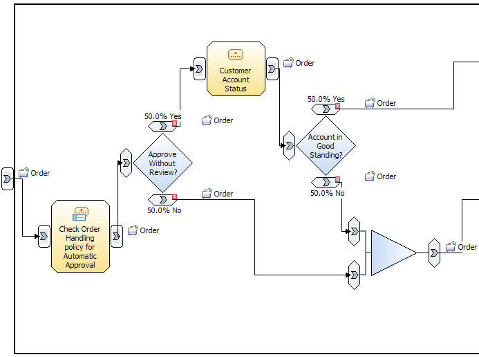
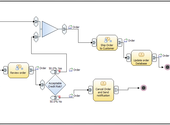
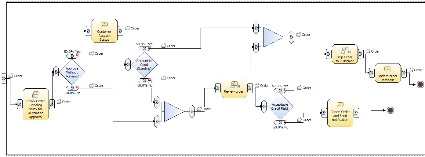
The following three images show the completed wired diagram. The first image shows the left half and the second image shows the right half. The third image is the completed wired diagram.