In this lesson, you will connect tasks, subprocesses, and other elements to model the flow of control and data through the business process.
Connecting tasks is also called wiring the tasks. There are two parts to wiring the tasks: you must create a wire to show that the output from one element becomes the input to another, and then you must indicate what data is passed between those two elements.
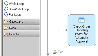
- Hover over the inner edge of the process diagram until you see an arrow.
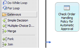
- Click and hold the left mouse button. Move the mouse with the connection to the Check Order Handling Policy for Automatic Approval task. Release the left mouse button to form a connection.
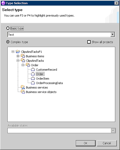
- Right-click the newly created connection and select Associate Data. Navigate to the ClipsAndTacksF1 project, select Order, and then click OK. Tip: An alternative method is to drag a business item from the project tree to a connection.
- Wire the remainder of the process diagram by repeating steps 1 and 2 for all of the elements, but review these tips before proceeding with wiring: Important:
- All of the links must have the Order business item with the exception of the link from Cancel Order and Send Notification to the Terminate node.
- If the Order icon is not automatically added to the link, add it using the Associate Data context menu option before continuing with the wiring.
- Press Ctrl+Z or click to reverse your last change instead of deleting recent work.
- If the Connections wiring tool is still enabled, select the white arrow icon at the top of the palette to enable the regular mouse pointer before you try to right-click an item. Alternatively, pressing the Esc key disables the connection tool.
- To prevent yourself from inadvertently creating extra input or output ports on the elements, click the center of each element that you are connecting.
The following three images show the completed wired diagram. The first image shows the left half and the second image shows the right half. The third image is the completed wired diagram.